

|
|
|
|
|
Main Menu |
Modbus RTU Protocol and the Honeywell SI FTAModbus RTU protocol is used extensively for industrial communications. It is one of the three main variants of Modbus protocol:
Direct RS232 or RS485 Links
Multiplexed Links Care has to be taken when using Modbus RTU over time-division-multiplexed links, since Modbus RTU protocol uses a time interval to mark the end-of-frame, instead of an end-of-frame character. Furthermore, the protocol definition (see below) calls for the Modbus message to consist of a more-or-less continuous stream of bytes. With multiplexed links, the sequence of bytes that form a single Modbus message may actually be sent as two or more groups of bytes, and a problem can arise if there is a significant delay between these groups of bytes when they arrive at the receiving device. Depending on the logic in the receiver, the bytes may be incorrectly interpreted as two or more packets rather than one. This can result in the Message Framing Errors or Message Timeouts, depending on the logic in the receiver.
Honeywell SI-FTA
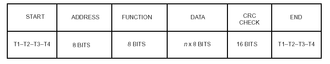
Analysis of the Problem RTU Framing The allowable characters transmitted for all fields are hexadecimal 0-9, A-F. Networked devices monitor the network bus continuously, including during the 'silent' intervals. When the first field (the address field) is received, each device decodes it to find out if it is the addressed device. Following the last transmitted character, a similar interval of at least 3.5 character times marks the end of the message. A new message can begin after this interval. The entire message frame must be transmitted as a continuous stream. If a silent interval of more than 1.5 character times occurs before completion of the frame, the receiving device flushes the incomplete message and assumes that the next byte will be the address field of a new message. Similarly, if a new message begins earlier than 3.5 character times following a previous message, the receiving device will consider it a continuation of the previous message. This will set an error, as the value in the final CRC field will not be valid for the combined messages. A typical message frame is shown below.
Modbus Framing in Practice
In practice, most Modbus communications drivers use only the 3.5 character end-of-frame delay when processing a stream of received data bytes.
Honeywell SI-FTA Intercharacter Delay This effectively reduces the 1.5 character allowable gap to a 0.5 character gap, and is the cause of many problems when interfacing to the SI-FTA, especially when using Modbus over a multiplexed communications network instead of with a point-to-point link.
Solution
Example Problem The telecommunications specification for the leased line included a group delay of 1200 microseconds, or 1.2 milliseconds. The link used Westermo modems, with a data rate of 9600 bits/sec. The Honeywell SI FTA was reporting communication errors. Analysis
As the link used parity, we therefore need to allow for 11 bits per character. The following table shows the corresponding character width, along with the width of a 0.5 character gap. For the link to work satisfactorily, the worst case group delay must be less than the inter-character time permitted by the SI-FTA. The following table summarises the inter-character delay as a function of baudrate, and also shows the expected performance of the link based on a 1.2 millisecond group delay. The link is deemed acceptable if (0.5 x CharacterWidth) is more than 1.2 milliseconds.
As there is not a lot of data (less than 100 registers), the most straightforward solution is to decrease the baud rate. In this particular case, reducing the data rate to 1200 bits/sec allowed the link to operate well within specificiation. Obviously, all active components in the communications link (master and slave devices and the modems) need to be reconfigured for the new baud rate settings, and may require a reset in order to start working at the new baud rate. |