

|
|
|
|
|
Main Menu |
Interfacing the Honeywell EPLCG to Allen Bradley PLC-5 and SLC-500IntroductionThis article discusses some practical aspects of interfacing the Honeywell Enhanced PLC Gateway (EPLCG) with Allen Bradley PLC-5 and SLC-500 Programmable Logic Controllers. This article discusses the Enhanced PLC Gateway (EPLCG), although the recommendations here can be also be applied to the standard PLC Gateway (PLCG). The EPLCG supports communications to Allen-Bradley PLCs using the PLC-2 subset of the DF1 command set. The DF1 protocol has a large, somewhat
unwieldy command set, supporting almost 60 different commands. The EPLCG uses three of the
oldest commands, namely those that were used for communicating to Allen Bradley's early
PLC-2 programmable logic controllers:
Newer Allen-Bradley PLCs, such as the PLC-5 and SLC500, still support the PLC-2 commands, although it may be necessary to make some modifications in the PLC and/or in the other network devices (such as the KF-2) in order to support this.
Commands Supported by the EPLCG
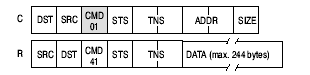
Unprotected Read
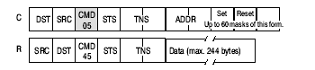
Unprotected Bit Write
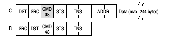
Unprotected Write Note that all three commands lack a file number.
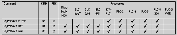
Commands Supported by various Allen Bradley PLCs
Probably the most important thing to note is that the SLC 500 does not support command 05, Unprotected Bit Write. The implication of this is that it is not possible to build digital composite or digital output points in the EPLCG that write directly to a bit within a word in the SLC 500. General Tips
PLC-5
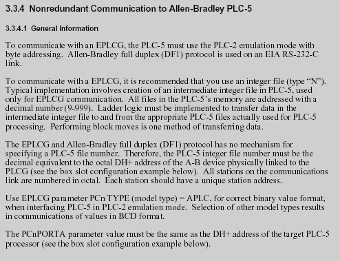
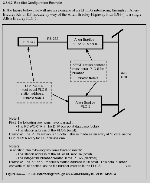
The following extracts from the Honeywell documentation describe the recommended setup for the KF-2 or equivalent KE module:
SLC-500 As noted above, command 05, Unprotected Bit Write, is not supported by the SLC-500 and so requires a workaround. Providing that the digital points are only operated through graphics, one suggested workaround is to write directly to the word in the SLC-500 (via a PLCG counter point) from the GUS embedded display. The subpicture used for these SLC-500 digital points would have parameters for the tag name of the counter point, along with the value to write. For example, if writing to bit 0 then write 1, or if bit 4 then write 16 to the counter. The following recommendations may be useful:
Note that the KF-3 automatically handles Embedded Responses, so no action is required.
References
|